
The precision of its initial integration defines the success of a municipal solid waste (MSW) recovery project.
We use advanced 3D material-flow simulation to eliminate operational bottlenecks before equipment manufacturing begins.
Our integrated plant designs focus on maximizing the purity of recovered RDF and mineral aggregates while minimizing the total physical footprint.
3D Spatial Layouts for Heavy-Duty Conveyor Belt & Machinery Integration
In an industrial msw waste sorting machine array, individual equipment units (like trommels and air separators) are only as efficient as the material transport network linking them. Traditional 2D plant plotting often overlooks the vertical clearance and velocity matching required between sequential processing stages, resulting in material spillage or conveyor wrapping.
To eliminate these spatial risks, our engineering division visualizes the entire system transfer sequence via advanced 3D model layout design files. This 3D environment allows project planners to scrutinize:
- Conveyor Transition Interfaces: Calculating exact drop heights and chute angles between the primary feeder plates and downstream screening units to prevent organic clogging.
- Velocity Synchronization: Designing specific variable frequency drive (VFD) controls for every heavy conveyor belt diagram to match the volumetric processing pace of the sorting line.
- Spatial Allocation: Routing long-distance transfer belts beneath structural platforms to minimize total facility floor area while ensuring 100% safe forklift and maintenance access.
Engineering Logic: From Waste Characterization to 3D Simulation
Standardized layouts often fail because waste composition is never standardized. Our engineering process begins with a Waste Characterization Analysis to determine the specific moisture content, bulk density, and PSD (Particle Size Distribution) of your local stream.
- Material Flow Logic: We employ linear and U-shaped flow configurations to prevent cross-contamination between organic fines and high-value recyclables.
- Volumetric Optimization: Our 3D models account for peak hourly loads rather than daily averages. This ensures that primary components—such as bag breakers and feeder plates—maintain a consistent volumetric flow into the sorting line.
- Modular Scalability: Every 3D layout includes pre-engineered “expansion zones” for future upgrades, such as optical sorting modules or secondary RDF refining stages.
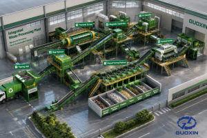
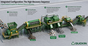
Integrated Configuration: The High-Recovery Sequence
An integrated waste processing plant is a synchronized ecosystem. Our 3D design ensures that the transition between each mechanical stage is seamless:
- Primary Liberation: High-torque shredding or bag breaking to release material for processing.
- Size Classification: Heavy-duty trommel screens isolate organic-rich fines (undersize) from the primary stream.
- Pneumatic Density Separation: Air separators utilize 3D layout logic to lift light 2D materials (film/paper) while allowing heavy 3D objects (stones/glass) to drop for aggregate recovery.
- Automated Ferrous Extraction: Magnetic separators are strategically placed before final shredding stages to protect equipment and recover high-purity scrap metal.
Technical Specifications & ROI Benchmarks
Use the following reference data to align your project requirements with the necessary plant footprint and equipment configuration:
| Processing Capacity (TPH) | Estimated Footprint (sqm) | Core Equipment Configuration | Primary Resource Outputs |
|---|---|---|---|
| 10 Tons/Hour | 1,500 – 2,500 | Bag Breaker + Trommel + Mag-Separator | Aggregates, Metals, Organic Fines |
| 20 Tons/Hour | 3,000 – 4,500 | 10T Config + Air Separator + Baling | High-Calorific RDF, Metals, Stones |
| 50+ Tons/Hour | 7,000 – 10,000+ | Full Automation + RDF Refining Line | Boiler-Ready RDF, Purity-Graded Metals |
Note: Power consumption and final footprint are finalized during the 3D design phase based on specific output purity requirements.
Request Technical Engineering Diagrams & 3D Assets
Planning the structural layout of an integrated waste processing plant requires precise CAD data. To assist your project engineering team, Guoxin Group provides access to verified plant design blueprints and modular equipment templates.
- Standardized
.dwg/.dxfCAD layouts for 100-500 TPD sorting plants. - Modular
.step/.iges3D engineering models for heavy trommel screens and conveyor structures. - Complete material flow block diagrams showing optimized mass-balance routing.
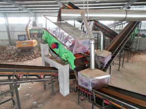
Real-World Implementation: Cases
Our design logic is validated by operational data from recent 2026 projects. In Guigang, Guangxi, and various other locations, our integrated sorting facility handles mixed municipal and construction waste, utilizing automated conveyor systems to transform raw debris into high-value construction aggregates and RDF for local power plants.
In Taizhou, the focus was on spatial optimization. By utilizing a multi-level 3D design, we successfully integrated a heavy-duty shredding line and an air separation system within a constrained urban site, achieving a landfill diversion rate exceeding 80%.
Request a Custom 3D Plant Layout & ROI Analysis
A professional sorting plant requires a project-specific approach. To receive a preliminary technical proposal, please provide your engineering requirements:
- Expected Daily Input (TPD)
- Primary Waste Composition (MSW, C&D, or Mixed)
- Required End-Products (RDF, Recycled Aggregates, or Metal Recovery)
FAQ
Q:How does the 3D layout design reduce on-site installation time?
A:By simulating every conveyor connection and equipment interface in a 3D environment, we identify potential physical interferences and material “dead zones” before fabrication. This typically reduces on-site commissioning time by 25-30% compared to traditional 2D planning.
Q: What separation efficiency can be expected for RDF production?
A:With our integrated air separation and trommel screening logic, the resulting light fraction (RDF feedstock) typically achieves a purity level of 90-95%, ensuring a consistent calorific value suitable for Waste-to-Energy (WtE) boilers.
Q: Can the plant design accommodate high-moisture organic waste?
A:Yes. For high-moisture MSW, our layouts incorporate advanced leachate collection systems under the primary feeders and trommels. We also adjust the incline angles of conveyor belts and the rotation speed of trommel screens to prevent material sticking.
Q: How is the system protected from damage by un-shreddable bulky waste?
A:The integrated design includes a PLC-monitored “protection loop.” If the primary shredder or bag breaker encounters a high-hardness object (such as a heavy steel block), the system automatically triggers a reverse-and-stop sequence while alerting the operator via the centralized control interface.
Q: What technical Formats are included in your preliminary plant layout proposals?
A: Every customized engineering proposal includes production-ready 2D CAD diagrams, technical sizing charts, and space-optimization 3D model layout designs for the entire integrated waste processing plant. These files specify exact equipment footprints, elevation clearances, and maintenance access zones tailored to your factory’s exact dimensions.
Q: Do your technical layouts specify the routing and synchronization of the conveyor systems?
A: Yes. Optimal material flow relies entirely on conveyor performance. Our comprehensive layouts feature detailed industrial MSW waste sorting machine material routing, including the spatial configuration, inclination angles, and motor drive specifications for every heavy-duty conveyor belt 3D model or diagram within the sorting sequence.