
Introduction
The efficiency of a Municipal Solid Waste (MSW) sorting plant depends heavily on the initial design phase. A well-engineered system not only separates recyclables like plastics and metals but also optimizes the production of Refuse-Derived Fuel (RDF) and minimizes the volume of waste sent to landfills.
Pre-Design Analysis
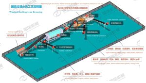
Figure 1: Standard process diagram illustrating the material flow logic from initial intake to final RDF production.
Before finalizing the plant layout, two primary factors must be analyzed:
- Waste Characterization: The moisture content, bulk density, and percentage of organic vs. inorganic matter determine the separation sequence.
- Input Capacity: Designing for peak hourly loads rather than daily averages ensures the bag opener and conveyors do not bottleneck during high-volume periods.
Plant Design Layout Considerations
Key factors include:
- Modular Scalability: Allowing space for future upgrades, such as adding optical sorters or additional shredding stages.
- Material Flow Logic: Ensuring a linear or U-shaped flow to minimize cross-contamination between sorted recyclables and residues.
- Environmental Control: Integrating dust collection and odor control systems within the plant’s structural footprint.
- waste composition
- processing capacity
- plant layout
- equipment configuration
- downstream recycling markets
MSW Sorting Plant Capacity & Footprint Reference Table
| Processing Capacity | Estimated Footprint (sqm) | Main Equipment Configuration | Power Consumption (kW) |
| 10 tons per hour | 1,500 – 2,500 | Bag Breaker + Trommel + Magnetic Separator | 120 – 180 |
| 20 tons per hour | 3,000 – 4,500 | 10-ton config + Air Separator + Baler | 250 – 350 |
| 50 tons per hour | 7,000 – 10,000+ | Full Automation + Robotic Sorting + RDF Line | 600 – 900 |
Note: The above data is for reference only. The actual footprint depends on the complexity of the waste components and the required purity of the output materials.
Integrated Equipment Configuration
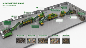
Figure 2: Our 3D design model highlights the spatial optimization and seamless conveyor belt integration within the MSW sorting line.
This 3D model ensures that each component—from trommel screens to air separators—is strategically placed to maximize throughput and minimize material bottlenecking.
A standard high-recovery design typically follows this technical sequence:
- Opening: Bag breakers release the waste for initial processing.
- Sizing: Trommel screens split the stream into undersize (organic-rich) and oversize fractions.
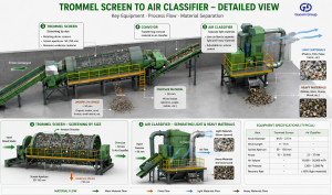
Figure 3: Detailed view of the automated conveyor belt system designed for high-abrasion material transport.
- Density Separation: Air separators isolate light 2D materials (paper/film) from heavy 3D objects.
- Ferrous Recovery: Magnetic separators extract scrap metal before the final shredding stage for RDF production.
Please fill out the form below or Contact to inform us of: waste composition, required processing capacity, and request an analysis report.