
In high-throughput municipal solid waste (MSW) and commercial/industrial (C&I) recycling facilities, material separation based purely on size classification is insufficient. After passing through a primary trommel screen, the material stream often retains a highly problematic, heterogeneous mix: lightweight, high-calorific plastic films and paper bundled together with dense, abrasive stones, glass shards, ceramic fragments, and heavy organics.
To convert this stream into high-purity Refuse-Derived Fuel (RDF) or clean recyclable commodities, plants deploy an air density separator (commonly referred to as an air classifier or wind sifter).
Unlike optical sorters that rely on chemical spectroscopy, or magnetic loops that isolate metals, a density separator relies strictly on aerodynamic fluid dynamics and terminal velocity differentials to split lights from heavies. Understanding the internal mechanics of this process is critical for operators looking to stabilize product purity and prevent severe downstream equipment wear.
The Physics of Aerodynamic Segregation
The separation mechanism inside an air density separator is governed by the relationship between three physical forces acting on a falling particle: Gravity (F_g), Aerodynamic Drag (F_d), and Buoyancy.
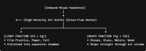
Every material has a specific terminal velocity—the air velocity required to suspend a particle in mid-air.
- The Light Fraction: Flexible plastic films (LDPE/PP) and paper possess a massive surface-area-to-weight ratio. Their terminal velocity is low (typically 2 to 5 m/s). When exposed to a controlled air stream, the aerodynamic drag force quickly overcomes their gravitational force (F_d > F_g), causing them to lift and entrain within the air currents.
- The Heavy Fraction: Inert contaminants like stones, glass fragments, and heavy composite polymers have a minimal surface area relative to their high bulk density. Their terminal velocity is high (exceeding 12 to 18 m/s). The drag force cannot overcome their mass (F_g > F_d), forcing them to drop vertically straight through the high-velocity air stream.
Step-by-Step Processing Inside the Separation Chamber
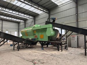
A professional air density separator executes this split through four synchronized mechanical zones:
Zone 1: Volumetric Feeding and Material Dispersion
Mixed material enters the separator via a high-speed acceleration conveyor belt. The belt operates at an elevated velocity (typically 1.5 to 2.5 m/s) to thin out the material layer. If the feedstock is too dense or matted, lightweight plastics will get mechanically trapped beneath heavy stones, preventing clean separation. The conveyor flings the dispersed material into the open separation chamber in a controlled parabolic arc.
Zone 2: The Controlled Air-Knife Vector
As the material falls through the air, it intersects an upward or cross-flowing blast of compressed air generated by a high-pressure ventilation blower. This blast passes through an adjustable nozzle called an air knife.
- The velocity of this air knife is variable and managed via an integrated Variable Frequency Drive (VFD). For standard MSW sorting, it is tuned between 15 m/s and 22 m/s.
Zone 3: The Split Separation Matrix
- The Drop Zone: Heavy stones, concrete chunks, coins, glass shards, and heavy metals cut right through the air-knife current. They fall directly onto the Heavy Discharge Conveyor positioned at the bottom of the chamber.
- The Flight Zone: Plastic bag fragments, paper labels, and thin foils are instantly redirected by the air momentum. They are blown upward and forward over a structural separation wall (splitter plate).
Zone 4: The Expansion Chamber and Air Deceleration
Once the light fraction clears the splitter plate, it enters a large expansion chamber. The cross-sectional area of this chamber expands dramatically, causing the air velocity to drop instantly below the terminal velocity of the plastics. Lacking the air velocity to remain airborne, the light plastic films drop out of suspension onto the Light Discharge Conveyor below, while the clean, filtered air is recirculated back to the main blower loop to minimize dust emissions.
Core Technical Parameters for Air Density Separation
To maximize separation efficiency while preventing material carryover, engineering teams must monitor several integrated operational metrics:
| System Parameter | Operational Baseline (Standard MSW) | Impact of Misalignment |
| Air Knife Velocity | 14 – 22 Meters/Second |
Too High: Heavies contaminate the light fraction. Too Low: Lights drop into the heavy fractions. |
| Material Moisture Limit | ≤ 35% – 40% (Optimal) | High moisture causes light paper to stick to stones, forcing misclassification. |
| Splitter Plate Angle | 35° – 55° (Adjustable via Actuator) | Optimizes the physical cutting edge between the drop zone and flight zone. |
| Air Circuit Style | Enclosed Negative-Pressure Recirculating | Prevents hazardous dust, odors, and micro-plastics from escaping into the facility. |
Operational Advantages: Why the Density Separator is Non-Negotiable
Integrating an automated density separator into your plant layout yields immediate operational cost reductions across your entire facility asset framework:
- Guarantees Premium RDF Calorific Value: By extracting up to 99% of non-combustible inert stones, glass, and metals, the chlorine and ash content of the light fraction drops significantly, while the Net Calorific Value (NCV) spikes. This ensures your final alternative fuel complies with stringent cement kiln off-taker agreements.
- Protects Secondary Shredder Knives: A single stone or piece of concrete entering a high-speed secondary single-shaft shredder can dull or chip a full row of tool-steel blades. Running an air classifier upstream ensures the shredder processes only soft polymers and paper, extending blade operational lifespans by up to 300%.
- Reduces Maintenance OPEX on Belts and Chutes: Abrasive glass dust and sharp stones cause rapid scouring wear on conveyor sidewalls and transfer chutes. Isolating them early confines abrasive wear strictly to reinforced, wear-resistant heavy collection bins.
Optimize Your Density Separation Efficiency
The mechanical efficiency of an aerodynamic separation loop changes depending on your regional waste composition, moisture spikes, and specific target outputs.
Reach out to our engineering team for a customized mass-balance simulation, 3D air-flow layout design, or an upgrade assessment for your current sorting lines.
EPC Project Infrastructure Team: Eve@guoxinmachinery.com