
In high-throughput Construction and Demolition (C&D) recycling and heavy industrial waste preprocessing lines, the primary shredder represents both the most critical sizing node and the highest localized operating expense (OpEx). Processing highly heterogeneous, abrasive streams—packed with reinforced structural rebar, concrete fractions, silica sand, and tramp metals—inflicts severe mechanical punishment on cutting tools.
Unoptimized cutter configurations routinely drive maintenance overheads to $1.50–$3.00 per input ton due to premature blade failure, structural cracking, and excessive downtime. Achieving a sustainable baseline below $0.40 per ton requires moving away from traditional single-alloy knives toward advanced dual-phase metallurgy and stress-relieving kinematic cutter geometries.
1. Metallurgical Failure Analysis: Why Mono-Material Tool Steels Fail
Many conventional shredder knives utilize mono-material through-hardened cold-work tool steels, such as AISI D2 (DIN 1.2379) or Cr12MoV. While these alloys deliver exceptional surface hardness (tHRC 58–60) suitable for uniform polymer films or municipal solids, they suffer from structural vulnerabilities when exposed to heavy C&D matrices.
Through-Hardened D2/Cr12MoV ──► Impact with Tramp Metal ──► High Local Stress ──►
Catastrophic Shattering [Bi-Metallic Cladding Matrix ──► Impact with Tramp Metal ──► Elastic Deflection ──► Predictable Linear Wear
The Mechanism of Catastrophic Brittle Fracture
Mono-material tool steels contain coarse, high-volume primary chromium carbides. This microscopic structure makes the material highly susceptible to impact-induced micro-cracking.
When a shredder tooth strikes a heavy structural steel section or an uncrushable quartzite boulder, the localized impact energy exceeds the material’s structural fracture toughness(K<sub>Ic</sub> is dangerously low at just 20–25 MPa·m<sup>1/2</sup>). This initiates subsurface micro-fissures that quickly propagate into catastrophic brittle fractures (spalling), rendering the entire cutter unrecoverable.
The Solution: Dual-Phase Cladding & Laser Hardfacing
To achieve the lowest lifetime cost per ton, heavy-duty industrial systems use a bi-metallic or clad structure that decouples impact resistance from surface abrasion defense:
- Core Base Matrix: The main body of the cutter is forged from a high-yield, high-fatigue-strength alloy like 42CrMo (AISI 4140) or H13 (DIN 1.2344), quenched and tempered to a ductile core hardness of HRC 40–45. This base serves as a structural shock absorber, possessing an impact toughness value of A_k ≥ 40 J to prevent body deformation or shaft-keyway breakage under peak loads.
- Hardfaced Cutting Edge: The active cutting edges undergo precision robotic laser cladding with a Tungsten Carbide Matrix (WC-Co) to a depth of 3 – 5 mm.
- Microstructural Properties: This layer consists of spherical tungsten carbide micro-particles (with micro-hardness exceeding HV50 1800–2200 suspended within a cobalt-nickel binder matrix. This dual-phase structure exhibits a macro-hardness of HRC 62–65, which prevents gouging abrasion from silica sand while resisting impact cracking.
2. Kinematic Shear Geometry: Reducing Specific Energy Consumption
Material selection must be paired with optimized cutting geometries. Poor blade geometry causes the shredder to crush material through compression rather than cleanly cutting it via shear strain. This increases peak torque demands, spikes electricity consumption (kWh/ton), and accelerates abrasive back-face wear.
[Standard Flat-Edge Cutter] ──► Compressive Crushing ──► High Torque Spikes & Rapid Blunting [Progressive Multi-Jaw Hook]
──► Tensile Shear Strain ──► Low Stress, Smooth Energy Draw
For high-abrasion, high-impact industrial and C&D applications, the cutting profile must utilize specialized angular parameters to minimize structural resistance:
Progressive Multi-Jaw Hook Geometries
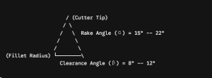
Instead of wide, flat single-point blocks, processing lines should deploy 3-jaw or 5-jaw indexable staggered configurations. The teeth are engineered with a forward-curved hook profile featuring a positive rake angle (alpha) optimized between 15^circ–22^circ.
- Kinematic Advantage: This aggressive rake angle enables the tooth to pierce bulk material and pull it against the counter-knives, inducing structural failure through tensile shear strain. Because the tensile strength of composite concrete and timber waste is significantly lower than its compressive strength, this geometry reduces structural cutting resistance by over 35%.
Clearance Relief and Stress Concentration Controls
The flanking clearance angle (beta) must be maintained between 8^circ –12^circ to minimize friction.
- If the clearance angle is too narrow, the rear flank of the cutter rubs against the compressed waste bed, generating high frictional temperatures that can cause localized annealing and softening of the hardfacing layer.
- To eliminate the risk of structural fatigue cracking under cyclical loading, the transition zone where the cutter body meets the main shaft rotor must feature a generous fillet radius (R ge 15text{ mm}), completely eliminating sharp internal step-corners.
3. Operational Asset & Lifecycle Cost Comparison Matrix
The technical data below reflects continuous mass-balance trials processing mixed C&D debris containing high-abrasion aggregate fractions ($\ge 60\text{ MPa}$ unconfined compressive strength) and embedded steel reinforcements:
| Performance & Financial Benchmarks | Option A: Conventional Tool Steel (AISI D2 / Through-Hardened) | Option B: Guoxin Engineering Matrix (42CrMo Core + WC-Co Hardfacing) | Option C: Standard Hadfield Manganese Steel (Mn13) |
| Hardness Profile | Uniform HRC 58–60 across cross-section | HRC 42–45 Core / text HRC 62–65 Edge Cladding | Base HRC 22–25 (Work-hardens to HRC 45) |
| Operational Lifespan per Cycle | 800 – 1,200 Hours (Prone to sudden fracture) | 4,500 – 6,000 Hours (Linear, predictable wear) | 300 – 500 Hours (Rapid blunting and rounding) |
| Catastrophic Failure Rate | 28.5% (High chipping risk on tramp rebar) | < 0.2% (Protected by VFD auto-reverse parameters) | 0% (Ductile, but deforms severely under high load) |
| Specific Energy Consumption | 18.5 kWh/Ton(Spikes as edges blunt) | 11.2 kWh/Ton (Sharp shearing profile retained) | 24.0 kWh/Ton(Relies on inefficient crushing action) |
| Net Operational Cost per Input Ton | Approx. 1.85 / Ton | le 0.38 / Ton (Optimized ROI) | Approx. 2.20 / Ton (High frequency maintenance cycles) |
4. FAQ
Why shouldn’t industrial operators build entire solid waste cutters out of solid Tungsten Carbide (WC)?
While solid tungsten carbide delivers unmatched micro-hardness, it lacks the tensile elasticity required for heavy industrial recycling. Solid carbides are brittle and have low resistance to shock loads. The unmanaged, high-frequency impact vectors encountered when processing C&D waste would trigger instantaneous structural failure across the cutter body. A dual-phase architecture—combining a ductile, high-fatigue alloy core with a specialized wear-resistant clad edge—is the only financially viable configuration for high-shock industrial applications.
How does integrating VFD auto-reverse protocols protect cutter metallurgy?
Cutter wear accelerates when a machine stalls and continuously forces its teeth against an unyielding object, generating severe heat friction and localized torque fatigue. Modern PLC control systems monitor current variations in the Variable Frequency Drive (VFD). If the current draws spike beyond 140% of nominal limits for more than 0.5 seconds, the controller stops forward rotation and automatically reverses the shaft array for 3–5seconds to reposition the material bed. This prevents the cutters from exceeding their structural yield points and mitigates thermal stress cracking.
Complete EPC Engineering and Turnkey Infrastructure
Maximizing asset uptime in abrasive waste environments requires a data-driven approach to component wear. Guoxin Group. delivers rugged, high-performance sizing and segregation machinery engineered to reduce long-term operational overhead. Our engineering divisions provide comprehensive 3D facility planning, localized mass-balance diagnostics, and wear-optimized cutter arrays matched to your precise material stream profiles.
Seeking to optimize the maintenance profile or upgrade the cutting configurations of your existing recycling plant? Contact our Senior Plant Design Division: Eve@guoxinmachinery.com