
Introduction
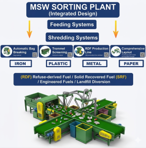
The efficiency of a Municipal Solid Waste (MSW) sorting plant depends heavily on the initial design phase. A well-engineered system not only separates recyclables like plastics and metals but also optimizes the production of Refuse-Derived Fuel (RDF) and minimizes the volume of waste sent to landfills.
Municipal solid waste (MSW) sorting plants play a critical role in modern waste management systems.
A properly designed MSW sorting plant can separate recyclable materials, recover combustible fractions, and significantly reduce landfill disposal.
Pre-Design Analysis
Before finalizing the plant layout, two primary factors must be analyzed:
Waste Characterization: The moisture content, bulk density, and percentage of organic vs. inorganic matter determine the separation sequence.
Input Capacity: Designing for peak hourly loads rather than daily averages ensures the bag opener and conveyors do not bottleneck during high-volume periods.
Plant Design Layout Considerations
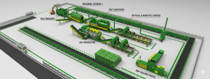
industrial style msw municipal solid waste sorting machine with conveyor belt 3d model or diagram or design
Key factors include:
-
Modular Scalability: Allowing space for future upgrades, such as adding optical sorters or additional shredding stages.
-
Material Flow Logic: Ensuring a linear or U-shaped flow to minimize cross-contamination between sorted recyclables and residues.
-
Environmental Control: Integrating dust collection and odor control systems within the plant’s structural footprint.
-
waste composition
-
processing capacity
-
plant layout
-
equipment configuration
-
downstream recycling markets
| Processing Capacity | Estimated Footprint (sqm) | Main Equipment Configuration | Power Consumption (kW) |
| 10 tons per hour | 1,500 – 2,500 | Bag Breaker + Trommel + Magnetic Separator | 120 – 180 |
| 20 tons per hour | 3,000 – 4,500 | 10-ton config + Air Separator + Baler | 250 – 350 |
| 50 tons per hour | 7,000 – 10,000+ | Full Automation + Robotic Sorting + RDF Line | 600 – 900 |
Note: The above data is for reference only. The actual footprint depends on the complexity of the waste components and the required purity of the output materials.
Integrated Equipment Configuration
For a 20t/h plant, the inclusion of an air separator is recommended to ensure the purity of the light fraction for RDF pellets
A standard high-recovery design typically follows this technical sequence:
- Opening: Bag breakers release the waste for initial processing.
- Sizing: Trommel screens split the stream into undersize (organic-rich) and oversize fractions.
- Density Separation: Air separators isolate light 2D materials (paper/film) from heavy 3D objects.
- Ferrous Recovery: Magnetic separators extract scrap metal before the final shredding stage for RDF production.