
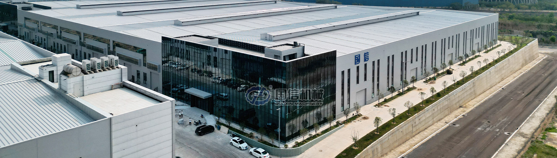
During the site execution phase of a municipal solid waste (MSW) or industrial waste recycling facility, structural misalignment between civil works and mechanical equipment accounts for over 40% of installation delays.
When heavy impact machinery—such as twin-shaft primary shredders, high-speed ballistic separators, and hydraulic horizontal balers—is mounted on improperly prepared concrete slabs, long-term vibration can induce concrete fatigue, structural cracking, and drive shaft misalignment.
As detailed in Step 9 of our Turnkey Waste Sorting EPC Project Execution Guide, executing strict civil-mechanical interface controls prior to equipment delivery is essential to guarantee smooth site installation and operational longevity.
1. Dynamic Load Calculation & Vibration Isolation Pads
Heavy waste sorting equipment exerts both static dead loads (weight of structure and full material load) and high cyclic dynamic forces. Civil design engineers must account for dynamic amplification factors (K_d) when designing supporting slabs and elevated platforms.
+-------------------------------------------------------------------------+
|                  VIBRATION ISOLATION FOUNDATION DESIGN                  |
|                                                                         |
|  [Equipment Base Frame (Shredder / Trommel)]                            |
|  =====================================================================  |
|  [Heavy Duty Elastomeric / Spring Anti-Vibration Mounts]                |
|  ---------------------------------------------------------------------  |
|  [Pre-Embedded Steel Anchor Plate (Flush with Finished Floor)]          |
|  ---------------------------------------------------------------------  |
|  [Independent Concrete Pad (Isolated by 20mm Expansion Joint Material)] |
+-------------------------------------------------------------------------+
Engineering Guidelines for Load Isolation:
-
Primary Shredders & Hammermills: Feature high instantaneous shock loads during shock impact with heavy un-shredded metals. Base slabs require a concrete strength class of at least C35/C40, with dynamic load design calculated at 2.0x to 2.5x static weight.
-
Ballistic Separators & Vibratory Feeders: Generate multi-directional reciprocating forces. These units must be mounted on independent concrete foundations isolated from surrounding building columns using 20mm resilient bitumen-impregnated fiberboard joints to prevent vibration transfer to the main warehouse envelope.
2. Pre-Embedded Steel Plate & Anchor Bolt Tolerances
Relying solely on post-installed mechanical expansion bolts for elevated heavy equipment is a common operational failure mode; continuous fatigue vibration frequently causes anchor loosening. The industry standard requires pre-embedded steel plates with welded rebar anchors poured directly into the concrete structure.
Anchor Plate Tolerance Specification Matrix:
┌──────────────────────────────────┬────────────┐
│ Dimensional Interface Parameter  │ Allowable Tolerance   │ Corrective Engineering Action   │
├──────────────────────────────────┼─────────────┤
│ Plan Position (X/Y Centerline)   │ ± 2.0 mm              │ Slotting base plate holes       │
├──────────────────────────────────┼─────────────┤
│ Top Elevation Offset (Z Axis)    │ + 0.0 mm / - 5.0 mm   │ Precision steel shim leveling     │
├──────────────────────────────────┼─────────────┤
│ Embedded Plate Levelness         │ ≤ 1.0 mm / meter      │ Grouting under support soles    │
├──────────────────────────────────┼────────────┤
│ Anchor Bolt Projection Length    │ ± 3.0 mm              │ Thread chasing / trimming       │
└──────────────────────────────────┴─────────────┘
Pre-Pour Positioning Protocols:
-
Steel Template Fixing: Before pouring concrete, supply the civil subcontractor with laser-cut steel locating templates to fix all embedded anchor bolts and plates rigidly to the rebar cage.
-
Post-Pour Survey: Conduct a 3D total station laser survey immediately after concrete setting. Any elevation discrepancy lower than design grade must be rectified using high-strength non-shrink epoxy grout during equipment positioning.
3. Pit Underground Trench Waterproofing & Drainage
Deep pits housing hydraulic fully automatic balers, apron feeders, or underground leachate collection tanks are vulnerable to groundwater ingress and aggressive chemical runoff from organic municipal waste.
           [Ground Level Finished Concrete]
                     │
                     ▼
  ┌─────────────────────────────────────────────────┐
  │ Baler Pit Wall (C35 Waterproof Concrete)         │
  │  ┌───────────────────────────────────────────┐  │
  │  │ Heavy-Duty Polyurethane Waterproofing Membrane│  │
  │  │  ┌─────────────────────────────────────┐  │  │
  │  │  │ Sacrificial Steel Wearing Liner     │  │  │
  │  │  │ (Protects against impact & abrasion)│  │  │
  │  │  └─────────────────────────────────────┘  │  │
  │  └───────────────────────────────────────────┘  │
  └─────────────────────────────────────────────────┘
                     │
                     ▼
   [Drainage Trench (1.5% Slope) ──► Leachate Sump]
Critical Pit Construction Checklist:
-
Waterproof Concrete Standard: Pit retaining walls must utilize self-waterproofing concrete (minimum permeability class P8/P10) with continuous rubber waterstops installed across all construction cold joints.
-
Corrosive Leachate Protection: MSW leachate has a low pH (acidic) and rapidly degrades exposed concrete. Pit floors must be coated with heavy-duty epoxy resin or fitted with a sacrificial stainless-steel lining plate.
-
Integrated Sump Pump Pits: All underground conveyor and baler pits require an integrated sump pit (600 mm × 600 mm × 600 mm) at the lowest point, angled at a minimum 1.5% drainage slope, fitted with an automatic submersible cutter pump.
4. Civil-Mechanical Handover Protocol
Before structural steel erection or machinery uncrating begins, a formal Joint Civil-Mechanical Handover Sign-Off must be executed between the Project Owner, EPC Contractor, Civil Constructor, and Equipment Installation Manager.
Protocol Sign-Off Steps:
-
Verification of Concrete Cure Time: Confirm core concrete strength has reached ge 85% design rating (typically 14-21 days post-pour) via cube compression test reports.
-
Centerline & Datum Line Verification: Verify the master building grid reference lines and zero-level (pm 0.000) elevation benchmark using optical leveling equipment.
-
Conduit & Trench Clearance: Ensure all underground electrical conduits and hydraulic pipe trenches are clear of water, slurry, and debris.
Technical Summary
Precision in civil foundation engineering directly dictates the efficiency and noise profile of a turnkey waste processing facility. Establishing clear interface tolerances and executing rigorous pre-pour surveys prevents expensive structural modifications once equipment arrives on site.
To review how civil interface handoffs fit into the complete 12-step project lifecycle—including EIA approvals, 3D BIM coordination, and commissioning—read our complete Turnkey Waste Sorting EPC Project Execution Guide, or consult with our field engineering team to receive complete foundation layout drawings for your equipment configuration.